From Concept to Prototype
From the first layer to a build-ready design, without leaving the software.
Build the Design
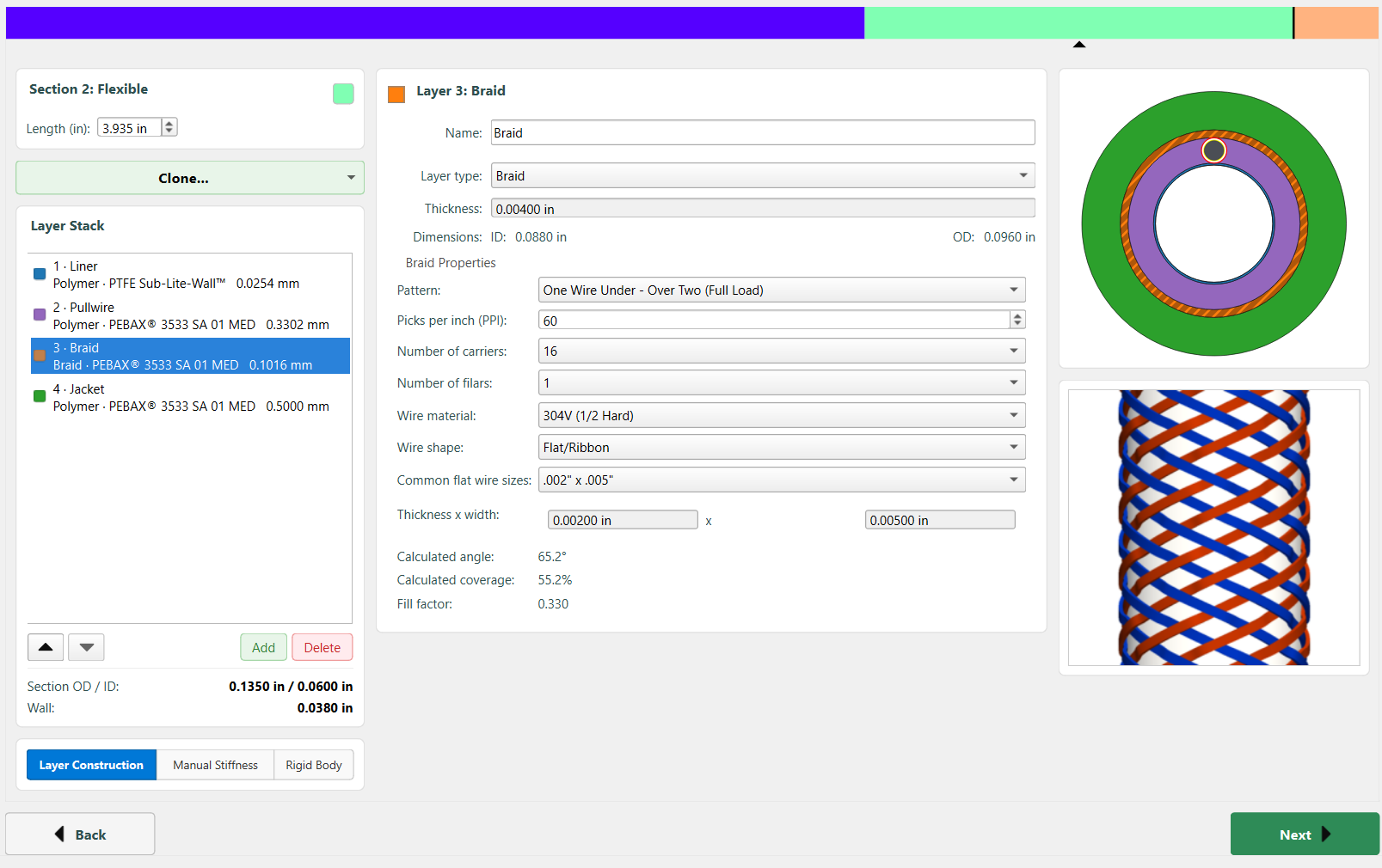
Layer by layer, segment by segment: liners, braids, coils, jackets, and pull-wires. The construction definition is the source of truth for everything downstream.
- Material Library: Pick from a library of common medical polymers, and add braid or coil reinforcements.
- Per-Segment Control: Independent dimensions, durometer, and braid PPI for each segment of the shaft.
- Live Preview: The cross-section and braid update as you build, so construction errors are visible before you calculate.
Instant Characterization
One click returns the full mechanical profile of the construction. The numbers that define how the device tracks, pushes, torques and bends.
- Mechanical Outputs: Bending stiffness, torsional rigidity, axial stiffness, and failure limits (kink, tensile, torque, burst, crush), per section and for the shaft as a whole.
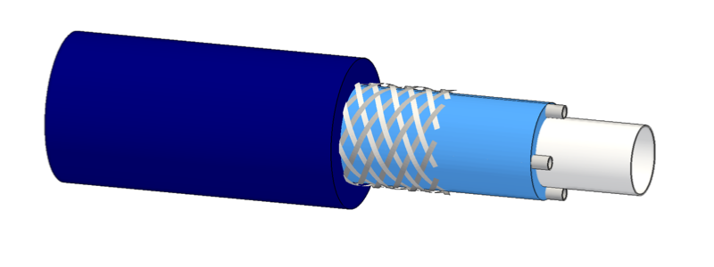
- Scale-Accurate Cutaways: 3D sections that verify layer interactions and show the team what's actually being built.
- One Consolidated Report: Every analysis you ran, exported as a single PDF or Excel document for design reviews and documentation.
Simulate Real-Time Dynamics
For steerable designs: drive the device on a virtual bench before it exists, and see how the physical build would behave.
- Virtual Actuation: On-screen controls let you drive the catheter through its full range of motion.
- Multi-Segment Behavior: Predict the curve shape across variable stiffness zones, including the interaction between different durometer segments.
- Pre-Build Confidence: Range of motion and actuation forces, established in software before you commit to the build.
Test It to Failure
Failure limits from a full simulation of your design, not a formula.
- Kink Radius: Which layer creases first, where the lumen halves (the ISO kink definition), and how the section fails, solved on the actual layup.
- Steering Behavior: Bend direction and bend radius, compound curves across stiffness zones, pull-wire tension, and the axial compression that tension puts into the shaft.
- Pushability: The force the tip can deliver before the shaft buckles, through a straight channel or a tortuous track, with vessel walls and friction.
Calculate Reflow Stackups
Get the pre- and post-reflow dimensions right the first time, before the PO for tubing goes out.
- Extrusion Sizing: The engine handles the volume math as thermoplastic flows into the structural voids, so the raw tubing comes in at the right ID and OD.
- Assembly Clearances: Tolerances modeled across the full stackup. The layers fit together at assembly, not at the second extrusion order.
- Heat-Shrink Spec: Expanded ID and minimum shrink factor needed for adequate reflow force.
Explore the Design Space
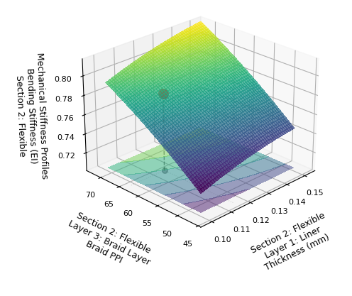
Once one design works, see what happens when you change it. Run a Design Sweep, a virtual DOE over your construction variables, to map the full performance landscape, not just the single operating point.
- Optimize or Stress-Test: Use the same DOE engine to find a better design, or to see how robust the current one is to construction variability.
- Multi-Variable Analysis: A change to one layer ripples through the whole shaft. See where it lands.
- 3D Response Surfaces: Find the operating point where performance and manufacturability both work, without running thirty physical builds to get there.
Export to Your Simulation Pipeline
Robotic navigation training, patient-specific planning, and reinforcement learning environments all need a catheter that responds like the real device. They are usually built on a single stiffness value for the whole device, which cannot represent a braided shaft with a graded tip. Export the calculated section properties instead.
- Per-Section Mechanics: EI, GJ, EA and mass per unit length along the full arclength, split by bend axis where the construction is anisotropic. Derived from braid PPI, wire geometry, coil, liner and jacket durometer. One JSON file, documented schema.
- Reads Into Solvers You Already Run: SOFA with BeamAdapter, NVIDIA Isaac for Healthcare, or MuJoCo.
- Scales to Training Runs: A scriptable CLI turns manufacturing tolerances on PPI, material properties, section lengths or wall thickness into fleets of device variants. A tolerance on the braid moves EI and GJ together the way a real production lot drifts, which adding noise to each stiffness independently never does.
A VirtuCath device model navigating a tortuous path in an external Cosserat rod solver. Navigation simulation is not part of VirtuCath.